Working the land: scraper or tractor?
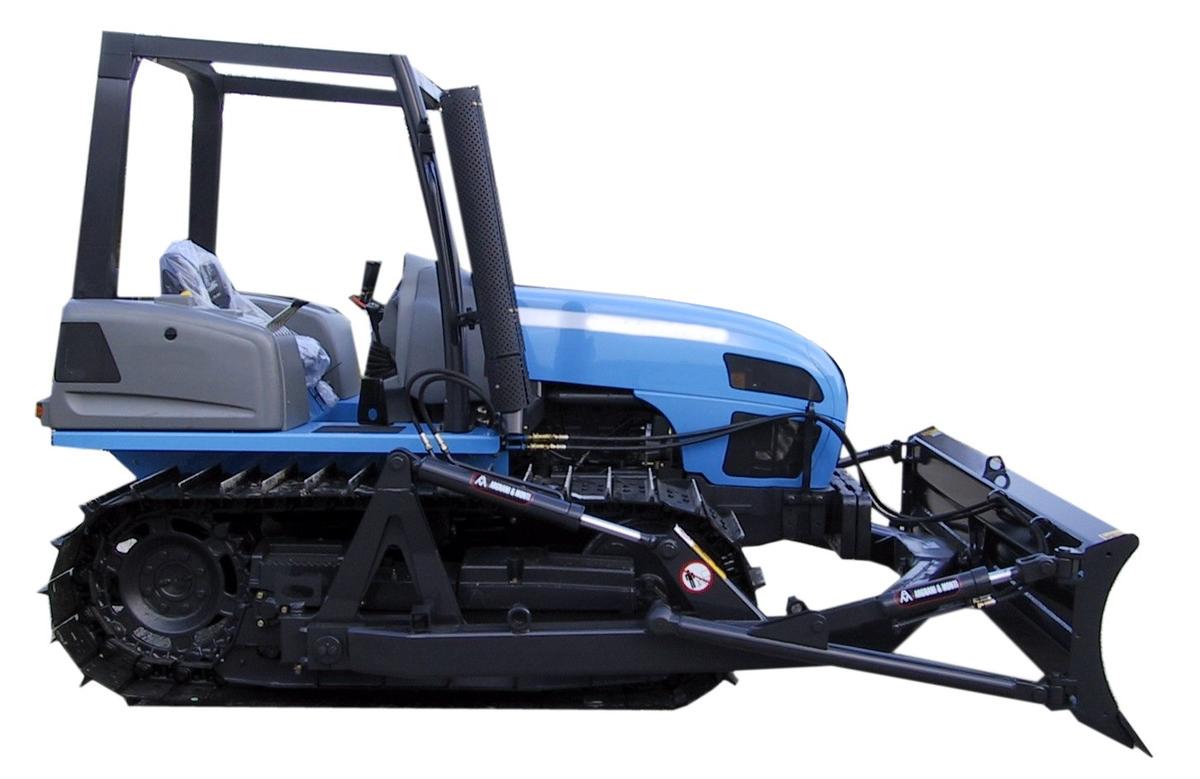
For replacing the heavy and bulky bulldozer a tracked agricultural tractor equipped with a dozer blade is capable of an excellent performance in many operating conditions. The Italian industry can point to a long tradition behind the most modern technical features for ensuring the optimum use of these tractors
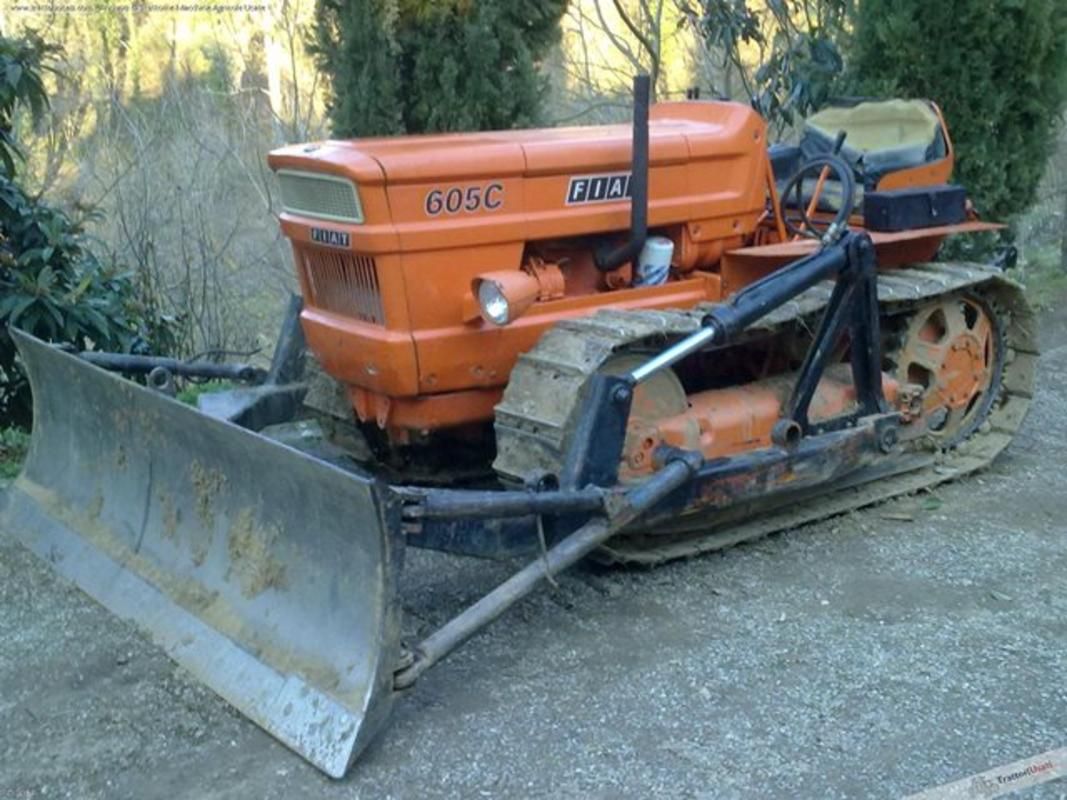
In the various sectors of the vast agricultural mechanization panorama a totally Italian tradition is still alive and well and that is the tracked tractor. Not at all the modern continuous rubber track, meaning tractors with hundreds of horsepower mounting rubber track, rather the small machines equipped with traditional steel track. Back in 1932 Fiat introduced in Europe the legendary 700C crawler tractor which evolved quickly as confirmed by the machine's technical and construction characteristics which turned out to be winners immediately after their appearance on the market. There were, in fact, very few units sold abroad as all these tractors, or nearly all of them, remained in the Mediterranean region because of similar operational and environmental conditions throughout the area. The crawler's raison d'être was made clear in work on hilly and mountainous terrain where the basic capability of the tractor stood out, that is, excellent longitudinal and transverse stability thanks to an especially low center of gravity. Adding in the substantial reduction of soil compaction makes it easy to understand that this was the ideal machine for vineyard operations and not those alone....
One of the special uses for a tracked tractor is undoubtedly as an alternative to the bulldozer. The need to work the land, on the surface and deep down, is often the case for farmlands as well. For this, the proper equipment mounted on a tracked tractor can be put to use in place of the more specific bulldozer and ensure good productivity. For this, however, a dozer blade is required.
The mounting framework
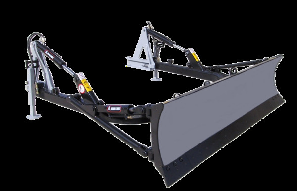
The scraper blade is designed to exert great force and is ideal for mounting on tracked tractors which, in optimum conditions, are capable of exerting pull and push force nearly equal to their weight, For this reason, the blade is solidly attached to the frame of the tractor to ensure a very robust and solid structure coming into contact with the ground. The shafting is simple and bolted on the tapped and drilled frame. If this is not present it will be necessary to weld on countershafts with their own tapping and drilling. The complete removal of mounting devices must, in fact, be guaranteed to avoid damage when this is not necessary as well as to make it possible to use the machine for other purposes, such as entering narrow rows without unwanted obstacles or bulk. Shafts usually include a plate varying in shape per track on which the blade itself is mounted.
At present, the solution most frequently adopted is a quick-hitch system for quick coupling and uncoupling with a series of pins on the shafting. By bringing the tractor up close to the blade sitting on the ground in the correct position the blade structure can be fitted into the purpose-built seats and securely locked in place by a supplementary device. To uncouple the blade, the procedure described above is simply reversed.
There are still blades with standard couplings on the market but these require a rather critical operation, including perfectly lining up the holes for inserting the blocking pins or bolts. In these circumstances some degree of savings will have been achieved but the time required for coupling is decidedly lengthy and, among other issues, the level of safety for the operator is lowered.
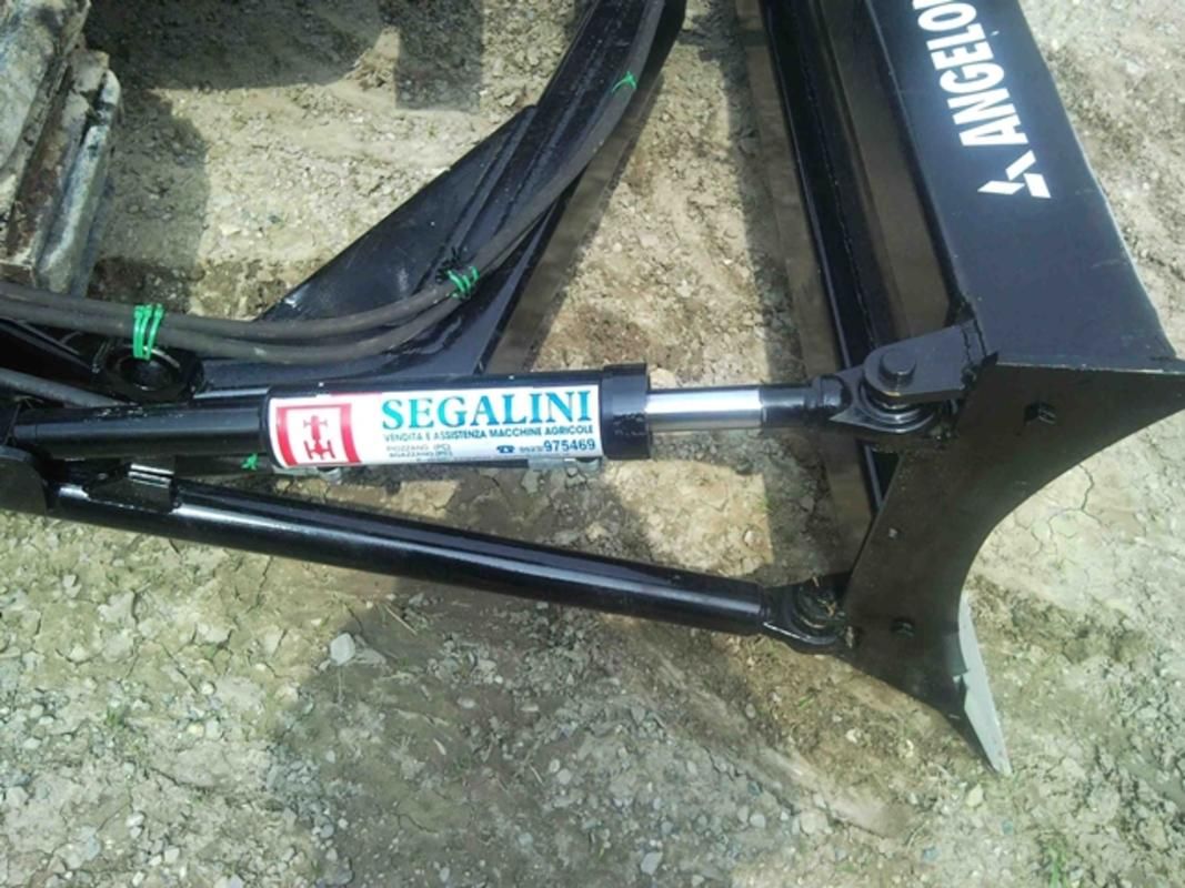
The blade itself is connected to the staffing by two more coupling staffs which contain the seats for the main staffing bolts or pins, those for coupling the blade structure and the upper frame, which is usually triangular. This structure supports the hydraulic cylinders required for regulating the blade's height of work. The linchpins are for coupling the mainframe in tubular hardened steel shaped into a U and wrapped around the front of the tractor. The front of the blade is hinged to this frame, can be fixed directly to the frame, coupled to joints with a degree of freedom (cylinder pins) or to a central spherical joint which allows it to be regulated along various axes (see box).
|
Systems for the inclination of the blades
Angledozer or tiltdozer? Or both? It might be useful to clarify: the first dozer blades produced could be regulated only on the vertical axis with hydraulics mounted on the mainframe. Nothing more is needed for many operations, for distributing a mass or earth or other materials to shift, for example. But for other requirements these blades were not sufficient, for levelling uneven ground or for unpaved roads where it is important to maintain a roadbed which is slightly inclined or humpback for rainwater drainage. For these operations what is needed is an angledozer blade which with transverse regulation to angle one end or the other to dig into the terrain off-center to create lateral inclinations. The tiltdozer on the other hand, again deploying hydraulics, makes it possible to tilt the blade in the direction of advance with one end at a greater distance from the tractor while the other is logically drawing nearer. In this way, the flow of material lifted on one side is shifted to the other which forces the transfer of the material from one side of the tractor to the other. What is required in the former case is a central spherical joint allowing inclination and for the second only a central hinged support is sufficient. Both movements are usually performed by hydraulic cylinders. Also to be noted is that many manufacturers tend to combine the two movements and refer without distinction to the tiltdozer so when purchasing a blade, the buyer must be careful to request exactly the blade with the characteristics wanted. |
The blade
The working implement of the machine is the blade itself, a robust curved steel sheet with one or more ribs solidly attached to a support frame for connecting to the mainframe. If the blade is attached directly to the frame this is by a number of support points; on the other hand, if the blade can be inclined, angle or tiltdozer, there are usually five points of support, a central joint and four lateral points linked to hydraulic cylinders and rods for setting the various inclinations.
The part coming into contact with the ground, called the plow or cutting edge, is usually built in milled hardened steel to protect it from wear; it can obviously be replaced when worn out. The blade is fixed in place by a number of bolts and can be built in one or more sections. Substituting a section on the later type is more efficient because only the worn part need be changed. This is useful if the blade has been put to repeated use in the inclined position.
|
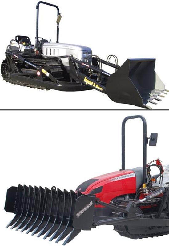
More blade, more functions
The standard blade usually mounted on these machines is the closed type which can efficiently move materials, clear the land and work on roads. Multifunctional blades, however, have become obligatory for agriculture as well as for agricultural equipment because the terminal implements of dozers are differentiated by now. The simplest version is the so-called destoner, a robust cutting edge of teeth for turning over the ground to a depth of 15-30 cm and removing large stones. With a few additional cylinders hoppers can be mounted for work as a front loader. For this purpose, the rear and front of the frame is modified to provide higher reach above. |
