vetti che rendono possibile la diagnostica in tempo reale di
tutte le parti dell’impianto frenante dagli attuatori alle su-
perfici di frizione, o che permettono una maggiore stabilità
in frenata del veicolo parzializzando in modo diverso la cop-
pia frenante sulle quattro ruote.
Per i trattori con cambio a variazione continua (CVT) è stato
sviluppato un sistema di controllo elettronico simile all’ABS
che, in caso di decelerazione del trattore, agisce sul rapporto
di trasmissione del CVT per modulare il rallentamento evitan-
do il bloccaggio della ruota (Brenninger et al., 2012). ùPer ga-
rantire una ripartizione ideale della frenata, un altro costrut-
tore ha invece brevettato di recente un sistema elettronico che
permette il trasferimento di parte della coppia frenante di-
sponibile dall’assale anteriore del veicolo verso l’assale po-
steriore o viceversa: questo risulta particolarmente utile qua-
lora il veicolo si trovi a muoversi in pendio e a causa di una
component materials, varying widely from manu-
facturer to manufacturer and the source of many
recent patents.
In recent years, researchers have converged on
covering friction areas with carbon fibre-reinforced
glassy carbon (graphite). Carbon is chosen be-
cause it is stable and low in density and because
unlike other materials it tends to increase its fric-
tion coefficient as the temperature increases, in
other words, offering sharper braking in more crit-
ical conditions.
Electronics Above All
ABS, or the Anti-Lock Braking System, has been
used on tractors since 2009, with the New Holland
T7 series. The system stops the wheels blocking
when the brakes are applied, reducing both skid-
ding and the braking distance.
It has been used on cars since the 1970s, but was only ex-
tended to tractors as their speed started rising. New Hol-
land was followed by other major manufacturers such as
Fendt, JCB, Steyr, Case IH and so on.
The biggest haul of patents on recent tractor designs has
gone to electronics, already in use or to come into use in
the next few years.
The patented devices include some that carry out real time
diagnosis of the state of the whole brake system, from the
actuators to the friction surfaces. Or else they achieve
greater stability by sharing out brake torque differently be-
tween the four wheels.
For tractors with a CVT or Continuously Variable Transmis-
sion, an electronic control system like the ABS has been
developed.
When the tractor slows down, it acts on the CVT’s trans-
mission ratio to modulate the speed reduction and stop the
wheels blocking (Brenninger at al., 2012). In the quest for
an ideal braking pattern, another manufacturer recently
patented an electronic system which shifts a portion of the
total brake torque from the front to the back axle, or vice-
versa. This is very useful when the vehicle is moving across
30
MW
n. 10_11/2013
S
PECIALE
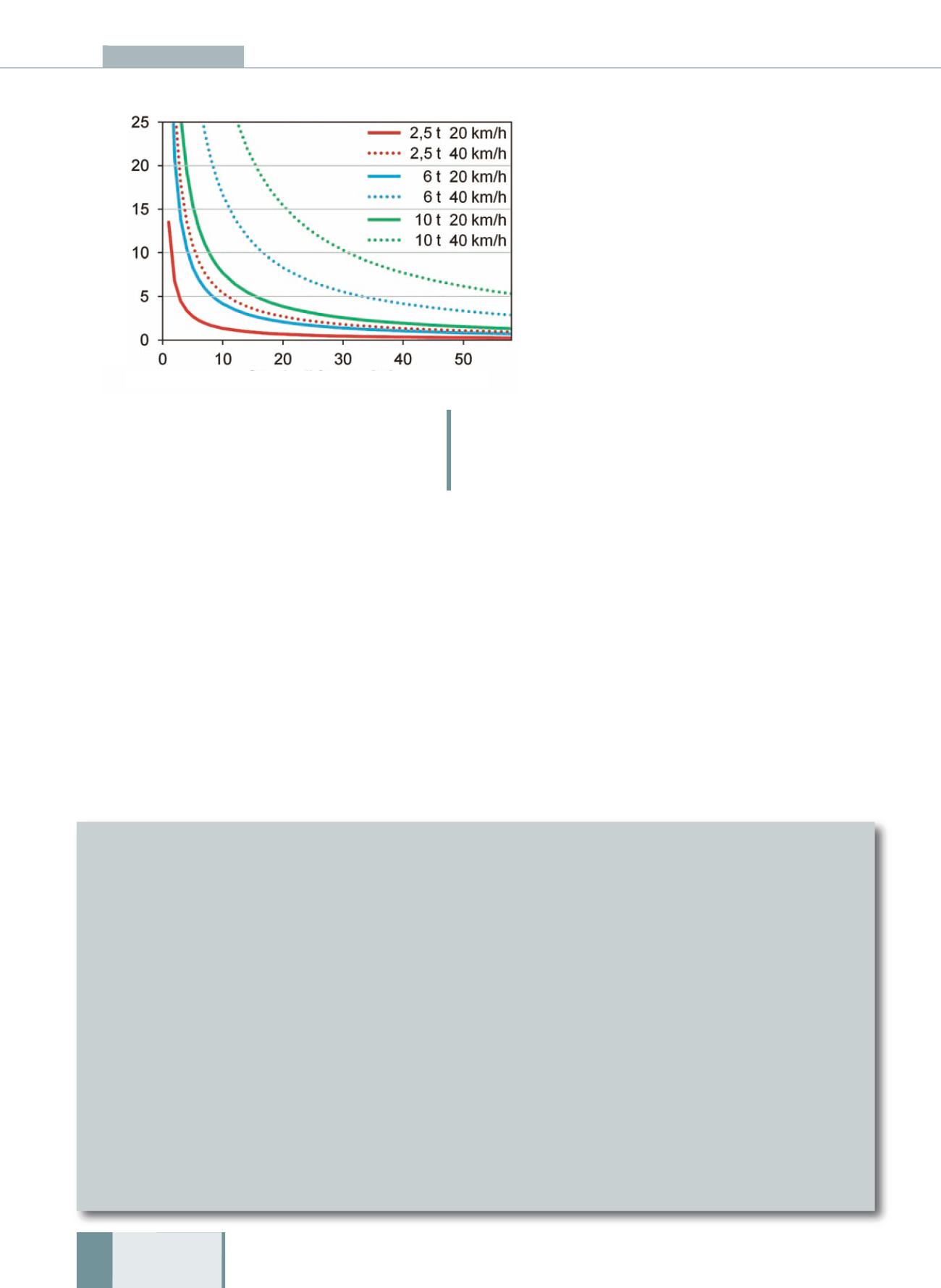
Figura 5: All’aumentare della massa e all’aumentare della velocità cresce
esponenzialmente la coppia frenante richiesta su ogni ruota, arrivando a
superare anche i 10 kNm per frenate entro i 20-30 m.
Fig. 5: As tractor weight and speed increase, the brake torque needed on
each wheel to stop the tractor grows exponentially, even topping 10 kNm to
stop in 20-30 meters.
Coppia necessaria per la frenata
Il momento frenante richiesto su ogni ruota per fermare un veicolo di mas-
sa m e velocità v è data da:
M = m v 2 · r /(k · s)
dove r è il raggio della ruota frenata, s è lo spazio di frenata e k è un coef-
ficiente che dipende dal numero di ruote frenanti, dalla distribuzione del
carico nel veicolo e dall’aderenza della ruota considerata, e varia tipicamente
tra 6 e 9 per trattrici a 4 ruote motrici. Si tratta di un modello teorico ma che
dà una stima dell’influenze dei vari fattori sulla coppia frenante richiesta.
Prendendo in considerazione tre trattrici con masse rispettivamente di 2.5
t, 6 t e 10 t, tutte con 4 ruote motrici e frenanti, e con ruote posteriori ri-
spettivamente da 140, 180 e 200 cm di diametro, la coppia frenante ne-
cessaria in funzione dello spazio di frenatura può essere rappresentata gra-
ficamente come mostrato in Figura 5.
Si vede come se a medie velocità (20 km/h) una coppia frenante di 5 kNm
è sufficiente a frenare in meno di 10-15 metri un trattore, a velocità più al-
te (40 km/h) sono necessarie coppie prossime ai 10 kNm per frenare in
20-30 metri i trattori più grandi.
Torque Needed to Stop
The braking power required on each wheel to stop a vehicle of mass m
and velocity v is given by:
M = m v 2 · r /(k · s)
where r is the radius of the wheel the brake is applied to, s the stopping
distance and k a coefficient depending on the number of braking wheels,
the distribution of the vehicle’s load and the grip exerted by the wheel
under consideration.
The value of the equation varies typically from 6-9 for 4WD tractors.
This is a theoretical model, but it gives an estimate of the influence of
the various factors on the required braking torque. Take three tractors
weighing 2.5, 6 and 10 tons, all 4WD with braking wheels, and rear
wheels respectively of 140, 180 and 200 cm in diameter, the needed
torque as a function of stopping space can be shown as in Fig. 5.
You can see that at medium speeds such as 20 km/h, torque of 5kNm
is enough to stop a tractor in 10-15 meters, while at higher speeds such
as 40 km/h, torque of around 10 kNm is needed to stop a larger trac-
tor in 20-30 meters.
Spazio di frenata [m]/
Braking distance
Coppia frenante [kNm]/
Braking torque


