
The three-point linkage, a key mechanical device
Both rear or front, the three-point linkage is the key to achieving the carried-type coupling between the tractor and the implement. Several hydraulic-driven devices and dedicated accessories make its handling safer and less tiring for operators, especially in the coupling and separation phases of the two units
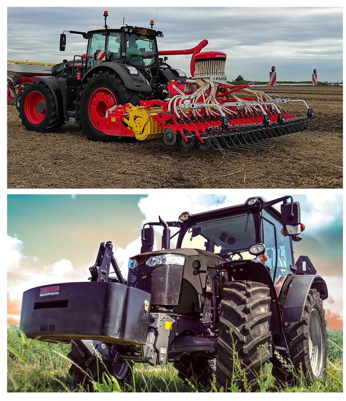
agricultural tractor's extreme versatility is not only expressed in the different options for transmitting power to the implements but also in the many ways they are connected. As a matter of fact, in addition to classic towing, which is made possible by a hook and towing eye integral with a drawbar, and rigid attachment with plates, brackets and bolts, the equipment can be coupled to the tractor via a 3-point hitch operated by the hydraulic lift. Besides generalized mounting at the tractor's rear, the 3-point hitch is increasingly being replicated on the front end to make possible the contextual mounting of two implements (and thus often the execution of combined work) or, alternatively, a monolithic front ballast.
The key parts
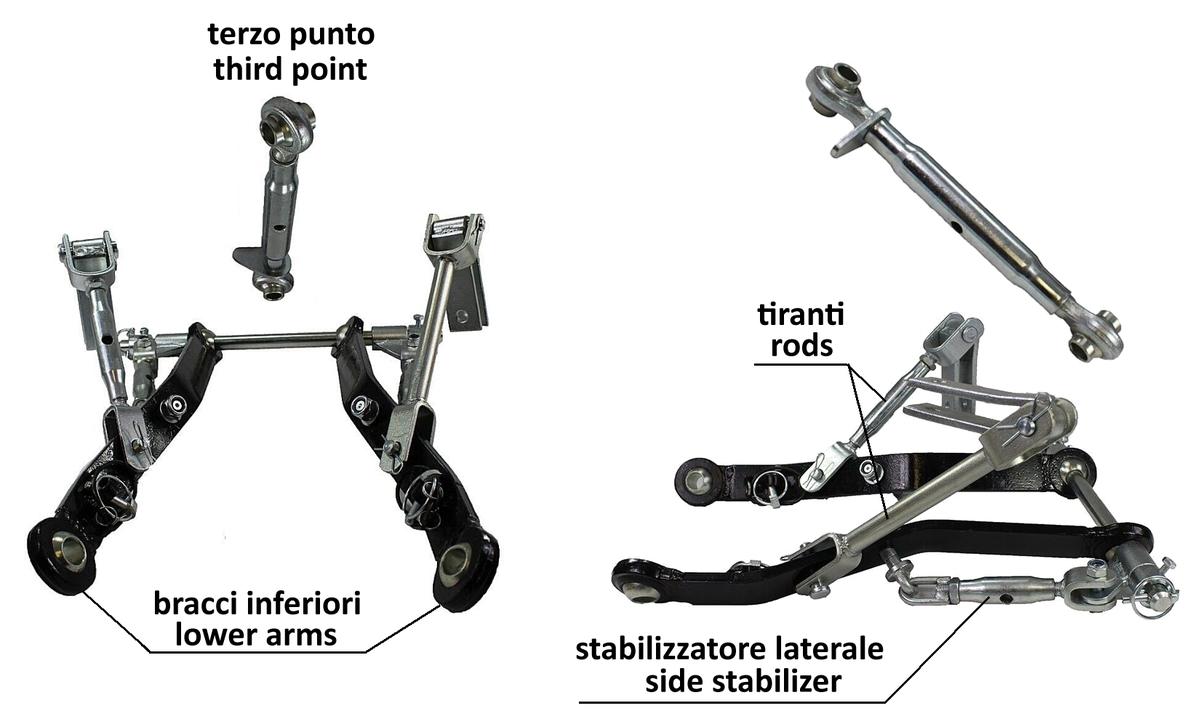
Basically, the three-point hitch consists of a pair of lower arms (or stems), a top link (or strut), and a set of adjustable tie rods and chains for movement by the hydraulic lift and limiting lateral sway. The lower arms are massive steel bars of rectangular cross-section hinged at one end to the tractor frame to allow convenient rotation within the intended operating arc. At the same time, the top link is a strong tie-rod also hinged to the tractor body, consisting of two oppositely threaded screws (one right and one left) with eyelets at one end, which screw at the opposite end into a central female sleeve. Thus, by rotating the sleeve in one direction or the opposite direction, the top link can be lengthened or shortened within a specified range to adjust the vertical alignment of the attached equipment conveniently.
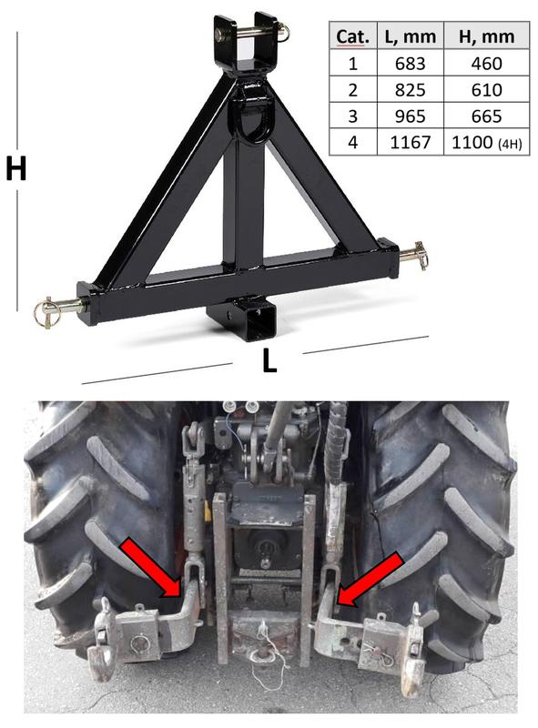
The ends of the lower arms and the top link thus define the so-called "attachment triangle," which logically must coincide (barring a certain tolerance) with the pins of the analogous triangular linkage frame of the operating machine. Thus, the three attachment points must be geometrically precisely defined to achieve a proper fit. Specifically, the size of the triangle's base (isosceles) and its height are important, which, together with other dimensions, are standardized at the regulatory level into "categories."
For farm tractors, 4 categories have been established, defined by the numbers 1, 2, 3 and 4, with progressively increasing sizes. Also of particular interest for models designed for specialized crops (orchards, vineyards, gardening, green maintenance, etc.) is the 1N sub-category, typical of so-called "narrow-track" tractors. Specifically, while the lower arms are straight and slightly divergent from the traditional categories, this sub-category assumes an S-shape configuration to combine the standard width at the rotules with the hinged attachments' reduced distance to the hinged attachments tractor.
The hydraulics support
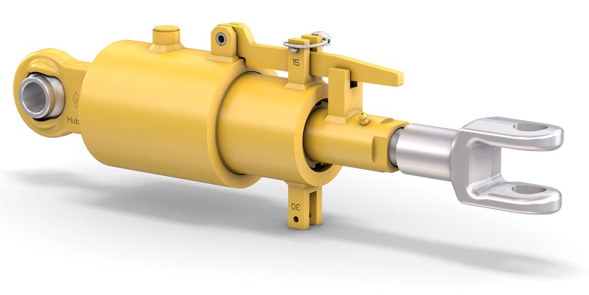
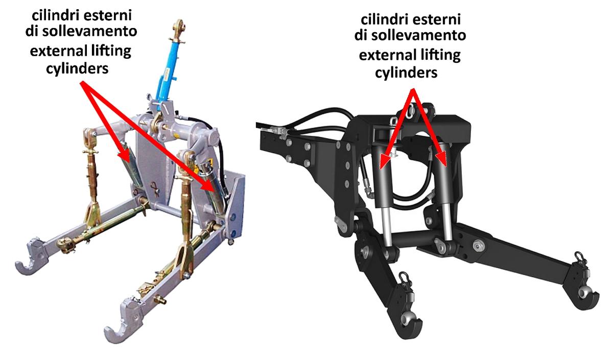
Although hydraulically operated by the lifter, the standard three-point hitch is a purely mechanical device, where the travel of the various adjustments is made using strong male bars and female sleeves, both threaded. As an alternative to this solution, for some time now, these movements can be carried out using hydraulic cylinders, starting precisely with the lifting function.
As a matter of fact, a modern alternative to the classic three-point hitch with mechanical tie rods moved with two upper lever arms on which the single inner cylinder acts concerns the replacement of the latter with one (i.e., on one side only) or with two external hydraulic cylinders, operating in contrast to the upper arms, which in this case are fixed.
Hydraulic third link with integrated shock absorber
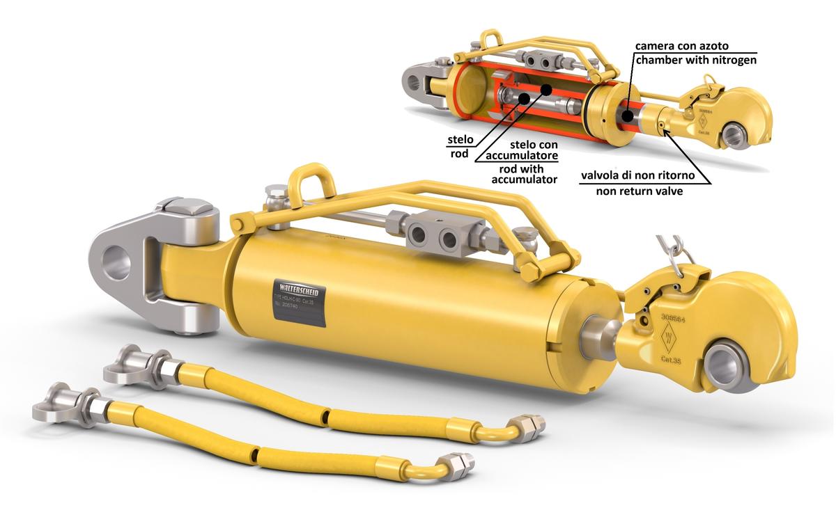
The hydraulic third link is now part of the equipment of any recently manufactured tractor. It offers a valuable aid to the operator, relieving him of a tedious, burdensome, and sometimes even dangerous task. Walterscheid has recently developed a hydraulic third link with an integrated shock absorber that can improve the implement handling in the carried coupling and make tractor driving safer (and more comfortable). This is because, thanks to the nitrogen accumulator, instantaneous load peaks transmitted from the implement to the tractor are effectively reduced, especially when working in the field and transferring on uneven surfaces. A check valve is installed (protected from dirt by a grub screw), which, in addition to allowing nitrogen recharge, can regulate the working pressure and, thus, the rigidity of the shock absorber. The piston acting in the cylinder is made of aluminum to decrease the device's overall weight while reducing friction and, thus, the overheating of the structure. This third link also has floating functionality, so basically, the triangular implement hitch frame acts passively in the same way as a trailer hitch, and the third link extends and shortens by faithfully following the relative changes in trim between the tractor and the implement when they are working on rough terrain. This option is extremely useful in plowing and forage mowing.
Hydraulic three-point hitch stabilizer
The lateral oscillations of the implement attached to the tractor's 3-point hitch must be carefully controlled to avoid dangerous collisions and creep between the lower arms and the adjacent inner sidewalls of the tires. The hydraulic version of the stabilizer ensures an active transition between the floating and rigid positions, regardless of the lift arm's length or the implement's ground clearance. A travel limiter can also be set when it is necessary to switch from Cat. 2 to 3 with regard to three-point linkage geometry.
Equipment attachment modes
The hitching and unhitching routine for carried implements usually involves the cooperation of two operators: the former is driving the tractor, while the latter is on the ground threading in the three attachment pins, with their safety pins, when the driver has backed the tractor up to match the attachment points.
The sequence described above is thus quite dangerous for the operator on the ground, who has to stand between the tractor and the equipment. If the driver fails to skillfully dose the tractor's minimum reverse speed, accidents, even serious ones, are possible due to crushing between the two machines of the person on the ground. Hence, it is self-evident that efforts have long been made to make it possible to perform the hitching/unhitching stages remotely, i.e., providing for driver intervention only, thus avoiding the presence of the unit on the ground.
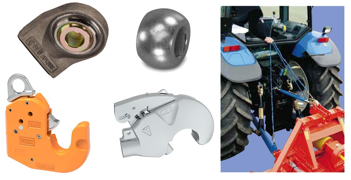
Typically, the equipment attachment triangle pins fit into rotules housed at the end of the lower arms and the third point. The rotules can rotate within limited angles to aid coupling with the pins. Alternatively, the rotules can be combined with strong, high-strength pressed steel hooks (to absorb high tensile, compressive, and lateral forces) equipped with a ratchet that can be controlled remotely by cables, operated by the driver sitting in the driver's seat. The internal mechanics, protected from shocks and debris, provide safety locking, complemented by centering guides and a kick-down function (lock on opening).
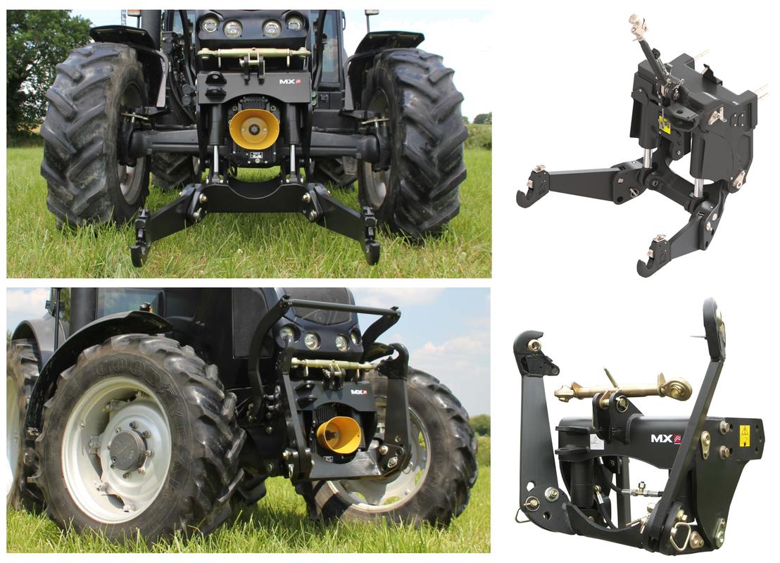
The front linkage
This is an increasingly popular attachment required to improve tractor versatility because it makes it possible to perform combined work, often in conjunction with a power take-off and/or one or more hydraulic sockets, or to mount a monolithic ballast.
To reduce the overall dimensions of the tractor, often the lower arms of this three-point linkage each consists of two sections, where the outer one can be folded back at least 90° when the linkage is not in use. Similarly, also the third link is easily removable. However, the hydraulic lift operating this type of linkage usually has poor operating alternatives than the rear linkage, being able to be operated only in position-controlled, floating mode.
The strain-guges on the 3-point linkage
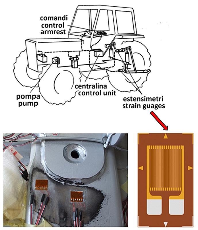
To control the load, the electronic lift that is now fitted to almost all new tractor models makes use of sensors, usually of the strain gauge type, which are intimately sticked (using special epoxy glues) to the surface of specific components of the three-point linkage, usually the lower arms or their hinge pins to the tractor body, but sometimes also the similar third link pin.
As a result of the dynamic stress, essentially tension or shear stresses, to which these elements are subjected, microscopic deformations (on the order of a few thousandths of a millimeter) are generated, which, however, generate a corresponding stress of the strain gauges integral to them.
Strain gauges are used to measure deformations (or even, similarly, compressions). When properly electrically powered, their added value is that they can proportionally transform these (micro) stresses into as many small changes in electric current, in terms of voltage or intensity, so that it is easy to correlate these changes in the electric signal to the corresponding changes in force, by the electronic control unit. The working principle of the strain gauge is based on the variation of the resistive value of the strain gauges by mechanical stress. To conveniently amplify this minimal variation, the strain gauge is made up of a track spread with many turns over a tiny surface area. Clearly, the support base of the strain gauge (i.e., a thin plastic substrate) and the adhesive binder must work together with the utmost fidelity in transmitting the (micro)strain while simultaneously ensuring adequate electrical isolation between the track and the reference metal surface.


