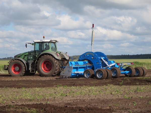
High precision for the machine graders
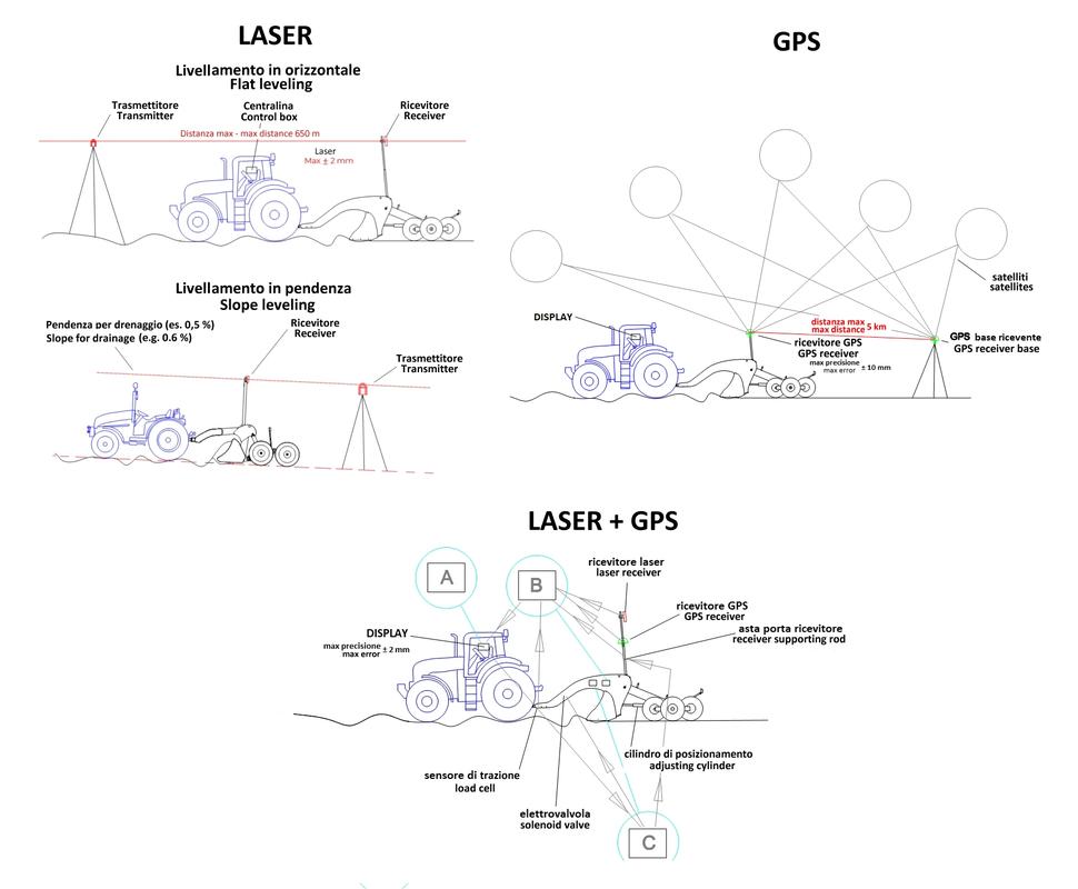
The combination of laser with GPS has led to a significant qualitative leap in the work of the graders. The laser provides a perfect definition of the plane, while the precise geolocation ensured by the GPS (in RTK mode) means the path of the equipment is optimized, to minimize the volume of material moved and consequently also the working times and costs
Being able to have perfectly levelled plots entails a series of important advantages, including correct water management, both in the adoption of different irrigation techniques and for what concerns rainfall, with a reduction of surface runoff and consequently of erosion, which removes inert material and nutrients. Furthermore, tillage carried out at unsuitable times and with not entirely appropriate techniques can lead to undesirable shifts in the soil, such as to require appropriate repositioning. Even the land arrangements, and in particular the merging of several adjacent parcels to form a single larger plot, may require large soil displacements, which are carried out together with the ground levelling. For these reasons the levelling of agricultural land has long been adopted even outside the rice cultivation, and with it also the use of graders, rarely self-propelled, sometimes mounted, but more often towed by a tractor.
The laser graders
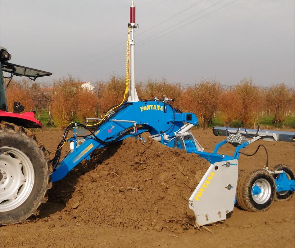
These are implements that can reach a considerable tonnage (up to 9000 kg), with working widths from 1.5 to 8 m, and which require coupling with very high-performance tractors (even up to 650 Hp), not so much for the power required, but rather for the ability to develop extremely high traction forces. In general, 30-45 Hp/m of working width are needed, even if for heavy duties (and with sturdy blades) this ratio can increase up to 70 Hp/m. In any case, the towing vehicle needs to be adequately weighted, to increase the gripping weight.
The job that the grader performs is relatively simple: compared to an extremely precise reference plane (with tolerances of the order of a few millimetres), it removes the soil where it is in excess and deposits it where it is missing, sometimes transporting it for several tens of metres. The main element of the machine is the blade, concave on the vertical plane, whose cutting edge "scrapes" the soil surface and accumulates the earth inside it, dragging the soil by rolling. The movements of the blade, both vertical and horizontal, are controlled hydraulically, through a system controlled with an electronic command unit which is based on the signals coming from a laser emitter/receiver assembly, which constitutes the technologically most advanced part of the grader.
The part of the blade in contact with the ground, the plough, is made of wear-resistant steel, and is bolted to the supporting structure, for easy replacement when it inevitably wears out.
The shape of the blade is characterized by a certain concavity and a certain angle of incidence. The radius of curvature obtained (which can be constant or variable, or consisting of different radii) causes the intercepted earth to move by rolling, rather than crawling on the surface of the blade, so as to effectively reduce friction, thereby decreasing the force of traction needed for the movement. On the other hand, the variation of the angle of attack (which can be carried out both mechanically and hydraulically) allows you to change the load capacity of the blade in the single pass: if you have to load a lot of earth (e.g. for large excavation works), perhaps with shifts of several tens of metres, it is convenient to set a high angle of attack, that is, with the ploughshare further forward than the upper part. However, a greater load capacity is detrimental to working precision; during the finishing phase there is a tendency to reduce the incidence, moving the ploughshare backwards with respect to the blade. Therefore, the load capacity decreases, but the earth falls more easily, levelling even the smallest depressions.
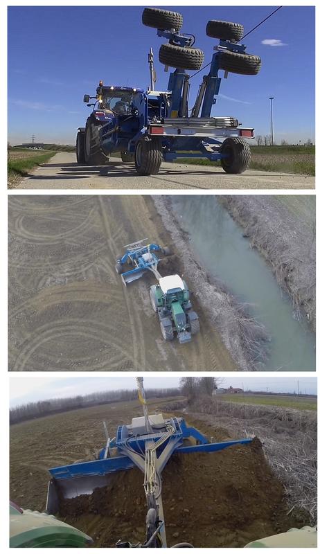
The blade is firmly fixed to a sturdy structure consisting of a gooseneck rudder at the front and a trolley at the rear, equipped with a variable number of tyres (from 2 to 8 based on the working width). The wider trolleys can be folded, either by means of a hydraulic extension (of the whole trolley or of a single wheel), or with pantograph, wing, or even lifting devices for the work trolley, with only two wheels on the ground for transport.
The arched shape of the rudder ensures adequate clearance to form the mound of earth to be moved; the "scraper effect" must be limited as much as possible, since it would entail excessive traction efforts. By placing an articulated joint between the blade and the trolley it is possible to tilt the blade obliquely, thus conveying the material on one side of the machine, a useful function when you have to move the soil in one well-defined direction.
The tilter is instead a device based on a hydraulic cylinder, which allows to slightly tilt the blade on the vertical plane. It is useful for working on headlands and near ditches or embankments: lowering the blade on the embankment side removes more earth, thus compensating for the natural tendency of graders to convey a greater quantity of material towards the edges of the field.
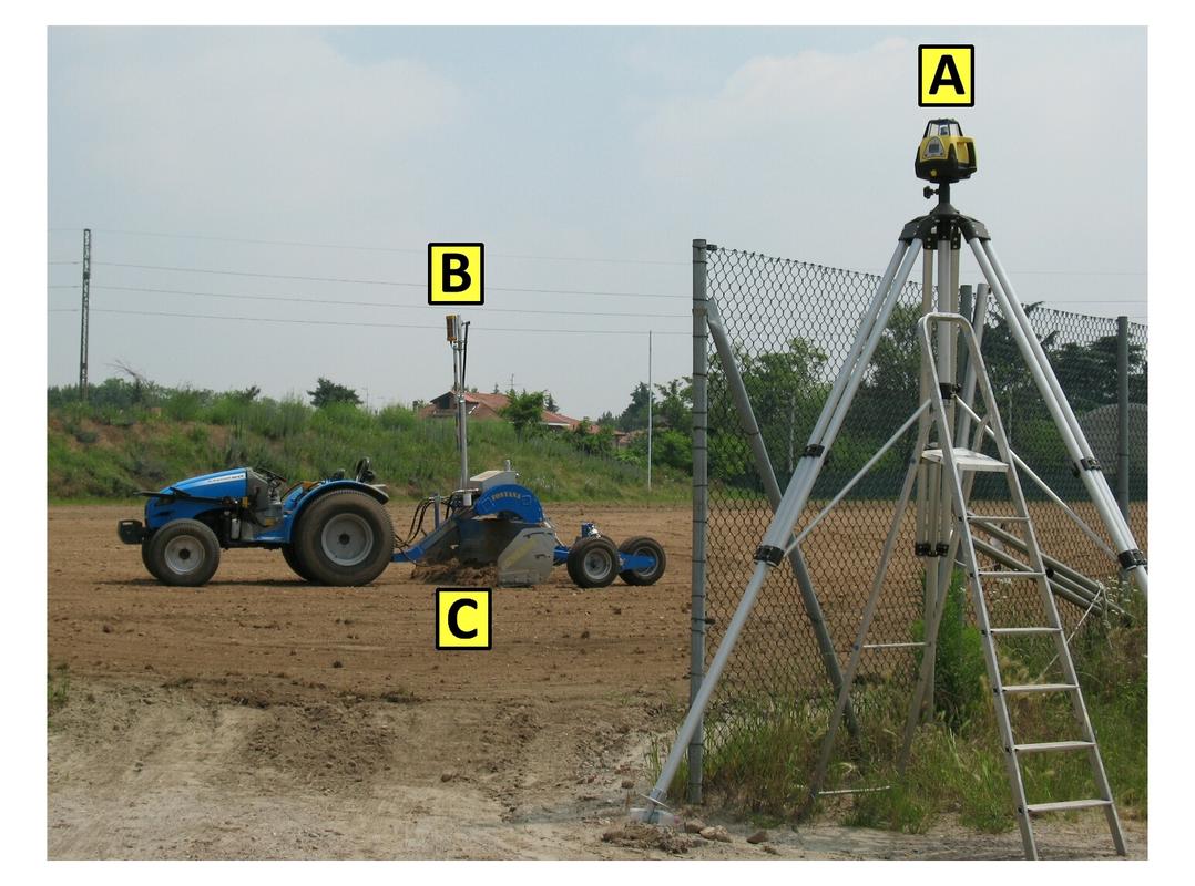
The laser
This is the instrumental part of the grader, which makes perfect smoothing possible by generating a concentrated and powerful beam of light, very bright and perceptible even several hundred metres away. The system includes the laser beam emitter, the corresponding receiver and a control box. In this specific case, inside the emitter there is a pentaprism crystal that reflects the incident laser beam at 90°, which rotates to create a 360° reference plane. Thanks to some photodiodes, the receiver picks up the signal (usually up to 6-700 m away) and through the movement of the blade it reproduces on the ground the plane generated by the transmitter. This is placed on an aluminium tripod, at a height about 2.5-3 m, such as to have free range and be detectable without obstacles. The most recent transmitters are self-levelling on the horizontal, but it is also possible to set planes with one or two slope values, in order to reproduce complex computer-developed plans with the utmost precision.
The receiver is fixed on the vertical part of the blade, by means of a telescopic rod with hydraulic control that enables changing its height, thus making it possible to level plots at different heights without having to move the emitter. Usually, a single receiver is mounted on the graders, but for greater working accuracy, some large models have two installed, usually at the ends of the blade. This also allows arrangements other than the horizontal, such as the "humpback" one, suitable for roads.
The signal picked up by the receiver is sent to the control box, to drive the proportional solenoid valve which acts on the blade positioning cylinders, to create the desired top with a tolerance of only ±2 mm.
To avoid an excessive load of soil, there is however a command to manually correct the position of the blade. The control box also optimizes the system with wind compensation, and automatically recovers the signal in the event of momentary absence.
In some cases, the hydraulic system is completely independent of the tractor, and is powered by a pump operated by the tractor's PTO. More often, this solution concerns exclusively the management of the hydraulic cylinder that regulates the height of the blade (with an oil tank integrated into the supporting structure). Meanwhile, the auxiliary services for opening the blade, adjusting the angle, etc. are managed through the distributors of the tractor system.
Road travel
To be able to travel on roads open to vehicular traffic, the best performing graders (with blades over 2.5 m in working width) are divided into sections (usually 3), with the two side wings foldable forward or backward. If the wings bend forward, when open they work "in abutment" and do not require pins for fixing, but in this case the equipment's rudder must be longer, to allow them to return to rest position. If, on the other hand, the wings have a backward folding, the drawbar can be shorter, but the pushing effort requires the presence of mechanical pins, which can also be activated automatically, to avoid unloading all the resistance of the loose earth on the hydraulic cylinders alone.
The towed connection between the drawbar of the grader and the tractor is ensured by a hitch, to be coupled to CUNA D2 or D3 category agricultural hooks (the most robust).
The drawbar hitches can be standard, or with multiple joints, to better follow the attitude variations that the machine assumes during the various processing phases.
In the latter case, a normal hitch, supplied as standard to replace the working one, must be used for road transfers.
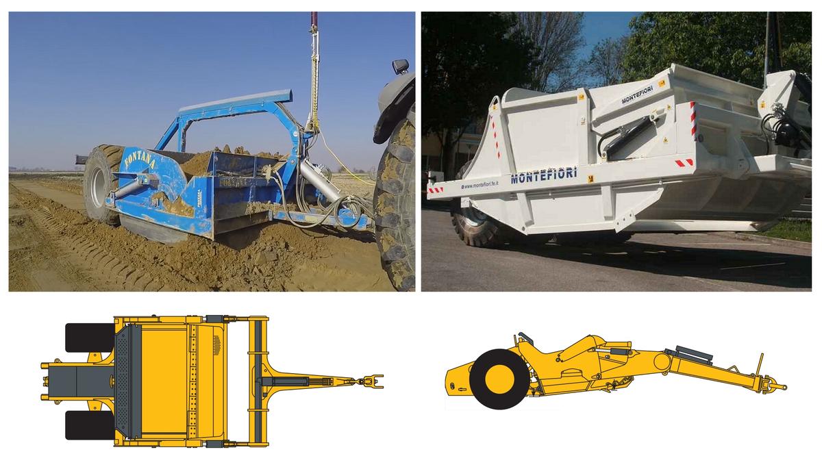
The scraper
It is also called "towed scraper", and it is a valid alternative to the grader when it is necessary to move large quantities of earth within plots for medium-long distances. For example, in the case of reclamation, land arrangements, construction of water basins, etc.
The scraper essentially consists of a roomy box, equipped on the front with a curved profile bulkhead that can be opened hydraulically, to allow the sharpened lower edge (sometimes also equipped with teeth for a more effective collection) to cut the soil, load it, transport it, and then put it where it is needed (also by spreading it out gradually) through another rear bulkhead that moves on steel wheels. All without dragging the material, as is the case with the grader. Like the latter, the scraper is also generally controlled by the laser, with a receiver that picks up the signal from the fixed station, usually located 3-400 m away.
Unlike the grader, with the scraper the soil is picked up only where it is really necessary, reducing the volume of material handled, also being able to easily create sloping surfaces.
Multifunctional use
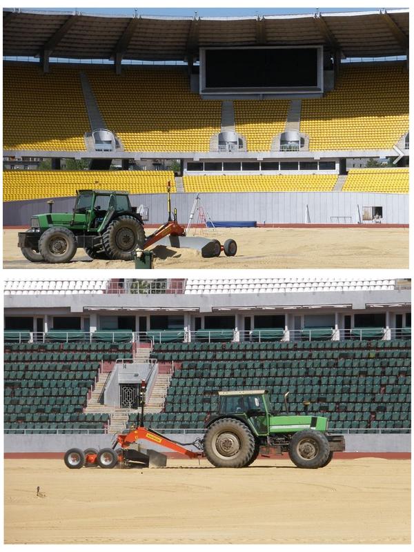
Not only soil, but also sand, gravel, and other inert materials. The grader is also beneficial when used outside the agricultural sector, in practice wherever it is necessary to flatten perfectly large surfaces. Therefore, it is useful for preparing the bottom of sports fields, constructing roads and airport runways, reconstructing beaches and marine coasts, flooring industrial warehouses, and creating parking areas, squares, courtyards, etc.
In addition to agricultural tractors, in these cases the graders are usefully combined with various earth moving machines, such as bulldozers, excavators, skid loaders, etc.
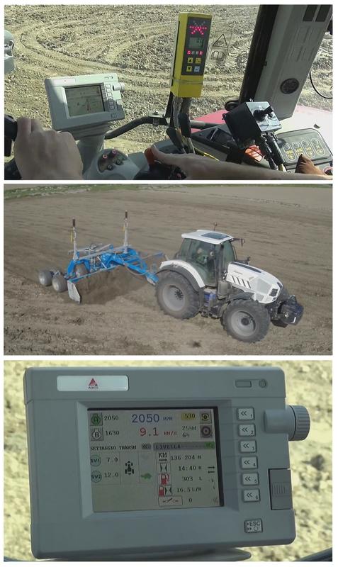
Laser-GPS integrated systems
Initially based on the ability of the laser beam to propagate for long distances in a straight line, for some years now graders have also advantageously made use of GPS (of the RTK type, i.e. high precision), as an alternative for the correct positioning of the blade, so that many models offer alternatively the two options. The main difference between the two solutions, however, is the precision of levelling in the vertical direction: with the laser, the tolerance is ±2 mm, while with the GPS it is approximately ±10 mm. On the other hand, the laser has a distance limit between emitter and receiver of a few hundred metres and suffers intense dustiness (which hinders the propagation of the optical signal), while by its nature GPS has no limit, being able to provide a global georeferencing. Moreover, the optimal solution is to combine the advantages of both systems: Mara Srl of Vercelli has developed software that uses the laser to define the plane, and the GPS to define the position of the machine on the plot to be flattened. The real added value, however, lies in the automation of the work, which can be carried out step by step on a 10" touchscreen monitor. The first phase of the processing consists in reading the levels of the soil on which to intervene, carried out by means of a guided drive around the field, in order to obtain a 3D map of the field specifying the slopes and the maximum distance between the excavation and fill areas, the volume of earth to be moved, the working time, and even the cost of the operation, depending on the characteristics (pre-memorized) of the grader and tractor used. After the operator enters any changes manually, the monitor will display the soil removal and fill areas, the area from which to start work (the one with the highest altitude), the current location of the site, and the most efficient route. Not only that, but the software will automatically manage the height of the blade (and therefore the amount of soil to be removed in a single pass) based on the tractor's pulling capacity and of course also of the working width of the grader. After each pass, the plane is updated, and with it the new path is optimized.


