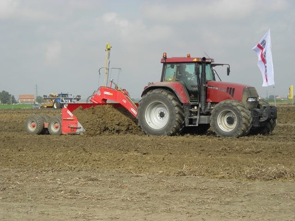
Laser level: guaranteeing an even field
Laser controlled levelling is turning into a major weapon in the farmer's armoury for reducing water waste and consumption
Water is an increasingly costly and rare resource needing increasingly careful management, to eliminate waste and reduce consumption. A direct approach to the problem is to rationalise how much watering is done, how it is done, and other correlate4d parameters. An indirect approach involves improved management of water use over the whole area - in which correct treatment of the surface soil is a major factor. Invented a few decades ago for rice paddies, the laser level, which is essential to ensure an absolutely horizontal surface for individual paddies and best water management, is now used widely for other crops. A perfectly even surface makes irrigation more uniform and should also limit erosion.
The equipment is almost always large, with a working width of 1.5-8 meters and a weight of up to 9,000 kg, requiring a high-powered tractor, even producing over 300 Hp. The machine’s job is to remove soil where there is too much of it and deposit where it is needed, using a robust blade. Even if there are manual models mounted on a tractor’s three-point hitch, most of them are hydraulically powered and controlled via an electronic unit using signals from a laser transmitter/receiver device.
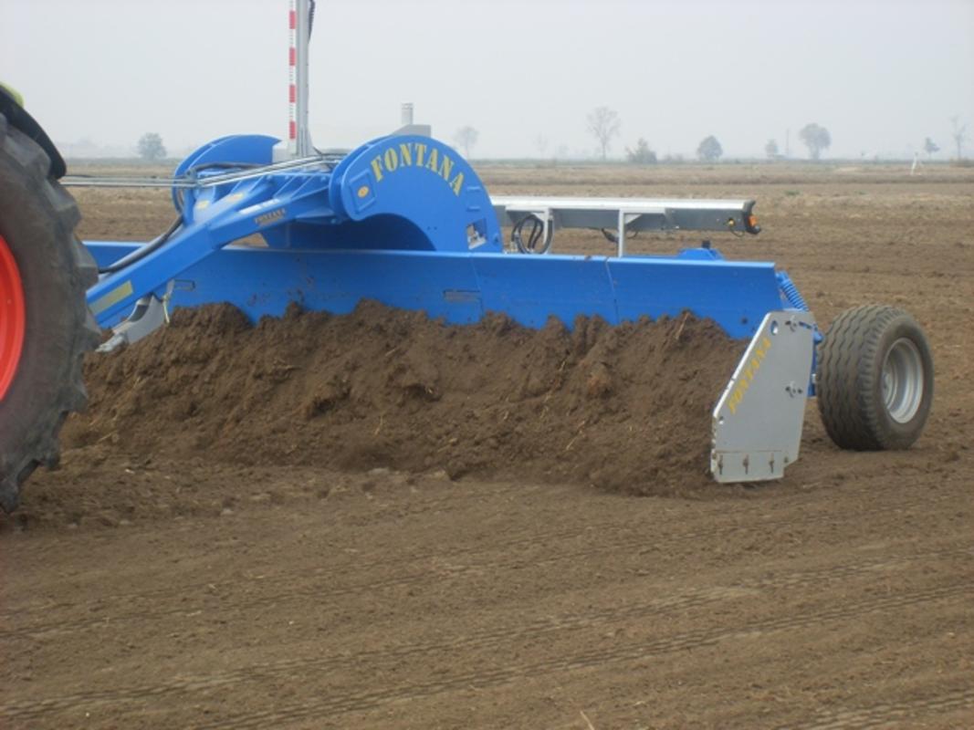
The Blade
The key component is the blade, which accumulates the soil in higher parts of the field for unloading in the lower parts. The share, in contact with the soil, is made of anti-wear steel and is bolted to the main structure so that it is easy to replace when it is worn down. The blade’s main structure is slightly concave. This makes it easier for the soil to roll across the surface, rather than dragging it, in an attempt to reduce the traction energy required.
BOX – The Blade’s Shape
The blade is concave and enters the ground at an angle. The curvature can vary with one or more curves, more than three radii being common in the search for a design, which will roll the soil across the surface, rather than cutting into it, which reduces friction significantly and with it the power needed. Typically, you need 30-45 Hp per meter of working width, though heavier jobs needing stronger blades may need 300 Hp for four meters.
The blade’s entry angle can be changed mechanically or hydraulically to modify the load on the blade at each pass. If much soil has to be loaded, perhaps shifting scores of meters, it is convenient to choose a high angle with the share ahead of the upper part of the blade. But bigger loading means less precision. In putting the final touches, the angle is usually reduced and the share is shifted back so that the load capacity falls, but the soil falls more easily and even minimal ups and downs in level can be levelled out.
Highway Use
The biggest blades measure over 2.5 meters and divided into sections, usually three. The two lateral wings can be folded forwards or backwards, which implies two different structural approaches. If they fold forwards, the wings require no fixing fulcrums, but the tow bar must be longer to allow for the wings to fit in; the load capacity is higher, but the tractor needs to apply greater power. When they fold backwards, the bar is shorter and the tractor can apply less power, but the machine needs mechanical, usually automatic fulcrums so that not all the pressure exerted on the ground is unloaded on the hydraulic cylinders.
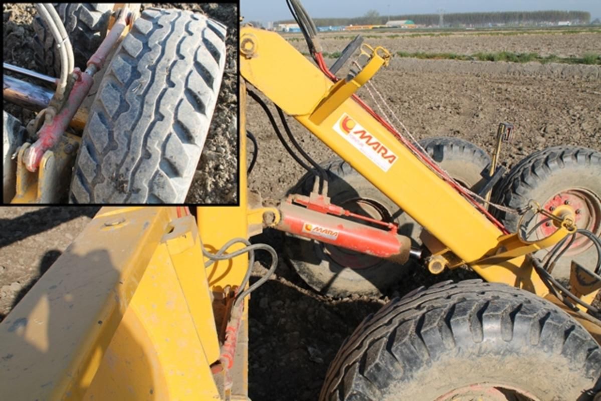
The structure holding the blade in place is a gooseneck tow bar and a carriage with a variable number of 2-8 tyres according to the working width. The blade’s stability and the quality of its work depend largely on the carriage width and the number of wheels. Over 4 meters, the carriage will be foldable, either with a hydraulic device for the whole unit or a single wheel, or with an accordion-style folding frame, or else by lifting up the carriage leaving only two wheels on the ground for transport.
The curve of the tow bar gives greater space for the formation of a pile of soil to be moved, another factor in limiting a bulldozer effect, which would require very high power. Putting a joint between the blade and the carriage makes it possible to incline the blade horizontally, forcing the material sideways, which is useful and necessary when shifting soil in a given direction.
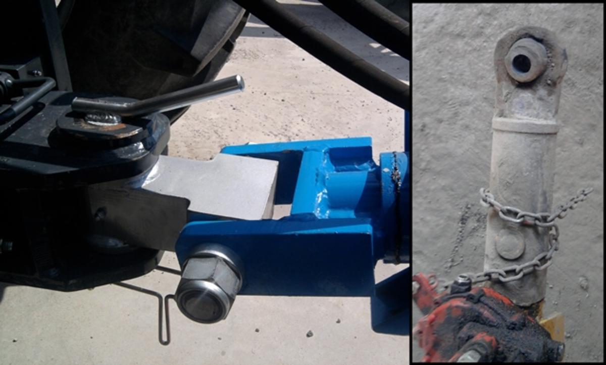
The linkage with the tractor is through a D2 or D3 agricultural hitch, the strongest. The hitch can be standard or articulated so that changes in position are followed better. In this case, they are rarely approved for highway use so that a normal hitch has to be used, if need be, replacing the working hitch.
The ‘tilter’ is based on an hydraulic cylinder acting on a link between the two wheels of a carriage so that the blade can be inclined slightly in one direction or another to regulate lateral positioning. It is useful at the end of a row or near ditches and banks. By lowering the blade near the ditch, more soil is removed, reducing the laser’s natural tendency to shift more material in that direction.
The Laser
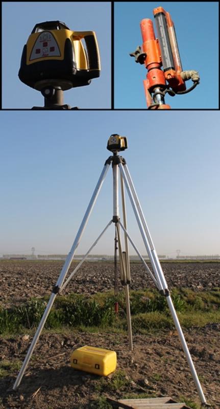
The laser is the machine’s technological hear, consisting of a transmitter, a receiver and a control box linked up to the blade’s hydraulics. The transmitter produces a rotating laser beam and is generally installed on the edge of the field on an aluminium tripod, higher than two meters, or enough to have a clear path over the tractor cab or any other obstacle. Automatic devices regulate it so that it is perfectly horizontal, although there are also transmitters that can work on a slope and follow exactly complex contour plans created by the computer. Transmitter power varies according to the model and gives a range of up to about 900 meters.
The receiver is attached to the leveller’s blade with a hydraulically controlled telescopic pole so that its height can be changed and various plots levelled without moving the transmitter. There is usually only one receiver, but some machines with a very wide working front may have two, on each end of the blade, for more accurate levelling, but also to get contours other than the horizontal, for example a contour appropriate for a road.
The signal from the receiver is sent to the control box to guide the proportional electric valve acting on the blade’s hydraulic cylinders. To avoid overloading, there is always a manual control to correct the blade’s position.
The general hydraulic plant usually consists of two sections. The main one is powered independently by a pump hitched to the tractor’s PTO with an integrated oil tank. This takes care of the hydraulic cylinder governing the blade’s height. The auxiliary services to open the blade, set the parameters etc. are linked to the tractor’s hydraulic distributors, although some models have a single, independent hydraulic circuit.


